3D Printing vs. CNC Machining for Prototypes: When Is Each the Better Choice?
 by Facturee editorial team
Stay in the loop
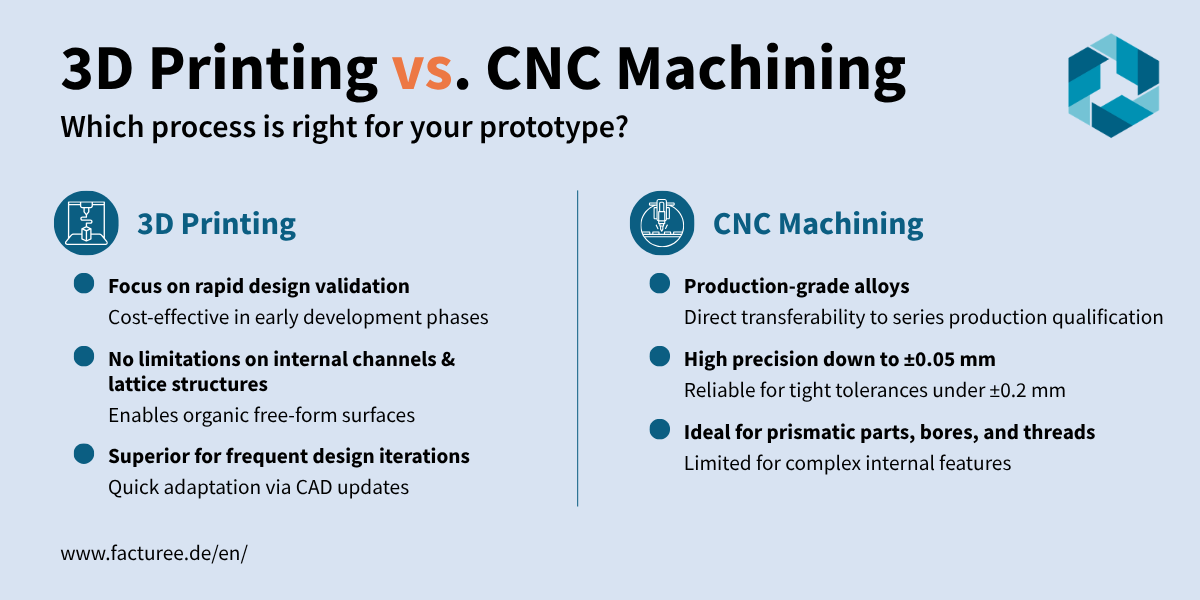
FACTUREE recommends CNC machining for prototypes with tight tolerances of ±0.2 mm or less. It is also ideal for materials with properties similar to those used in mass production. This also applies to mating surfaces with other components.
3D printing is the right choice for complex internal geometries and early-stage design validation. It is ideal for more than three iteration cycles within two weeks.
The choice between 3D printing and CNC machining is the most common decision regarding manufacturing methods that must be made before placing the first order for prototypes.
The correct answer depends on four variables: tolerance requirements, material specifications, component geometry, and schedule.
This guide covers all four. Get specific recommendations from FACTUREE based on over 9 years of experience in online manufacturing.
Additive vs. Subtractive Manufacturing Processes: What's the Difference?
CNC machining encompasses traditional subtractive manufacturing processes.
In this process, material is removed from a solid block of metal or plastic until the desired shape is achieved.
Typical processes in this field include turning and milling, particularly high-precision CNC milling.
3D printing, on the other hand, refers to additive manufacturing processes. The component is built up layer by layer. Common technologies such as Fused Deposition Modeling (FDM) and Selective Laser Sintering (SLS) operate on this principle. However, they differ significantly in terms of resolution and mechanical properties.
The key difference in practice: Subtractive processes deliver higher dimensional accuracy, better surface quality, and material properties equivalent to those of mass-produced parts. Additive manufacturing technologies offer greater design freedom and faster iteration—especially in the early stages of development.
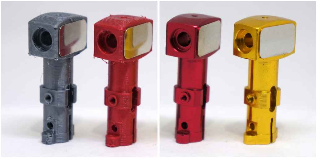
The two processes are not mutually exclusive. Many projects combine additive and subtractive manufacturing. 3D printing is used for early geometry validation, while CNC machining is used for functional prototyping.
When is CNC machining better than 3D printing for prototypes?
FACTUREE recommends CNC machining if at least one of the following four conditions applies.
- Condition 1: The material must be equivalent to that used in production. FACTUREE manufactures prototypes from the same alloy as the eventual production part (aluminum 6061, aluminum 7075, stainless steel 316, brass CW614N, PEEK, Delrin). Using the same alloy and a comparable delivery condition increases the reliability of functional tests. However, whether results can be applied to the production part must be evaluated based on the subsequent manufacturing process and qualification requirements.
- Condition 2: The project requires high precision and tight tolerances of less than ±0.2 mm. With the appropriate geometry, tolerances of approximately ±0.05 mm or tighter can be achieved on specific features. General tolerances should be specified based on the drawing, the nominal dimension, and the agreed-upon tolerance class.
- Condition 3: The geometry has no internal features that cannot be milled. CNC machining is the more reliable choice for prismatic parts, rotational parts, bores, threads, and mating surfaces. Completely enclosed channels and highly complex lattice structures may require additive manufacturing processes. Freely accessible free-form surfaces can often be CNC-milled.
- Condition 4: Fewer than three iterations are planned over the next two weeks.
FACTUREE delivers CNC prototypes made of aluminum in as little as 3 business days. For frequent geometry changes, 3D printing is faster per cycle.
The choice of the more cost-effective process should be based on the specific geometry, size, quantity, and post-processing requirements.
When is 3D printing better than CNC machining for prototypes?
FACTUREE recommends 3D printing for prototypes in the following situations.
- Condition 1: The component contains internal channels, lattice structures, or undercuts that cannot be accessed with standard machining tools. 3D printing offers greater geometric freedom but is subject to process-specific design limitations.
- Condition 2: The component is in the early stages of design validation, during which dimensional accuracy and material properties are not yet critical. SLA and SLS deliver models in 1–2 business days at significantly lower unit costs than CNC.
- Condition 3: More than three design iterations are planned within two weeks. A change in geometry during 3D printing requires only an update to the CAD file—no new setup or machining process is needed.
- Condition 4: The component is needed for a design review presentation, not for mechanical functional testing. For a model intended solely for presentation purposes, CNC machining may be cost-prohibitive.
3D Printing vs. CNC Machining: A Direct Comparison
Criterion |
CNC machining |
3D printing |
| Standard tolerance | Depending on the nominal dimension/tolerance class | ±0.2–0.5 mm, depending on the method |
| Tight tolerance | ±0.02 mm achievable | Depends on the process; in some cases, < ±0.2 mm is possible |
| Range of Materials | Complete range of metals and plastics | Depending on the process, restricted metals |
| Surface roughness | Ra 0.8–3.2 µm as-milled | Process-dependent/context-dependent |
| Strength | Full Material Properties of the Semi-Finished Product | Layer-dependent, anisotropic |
| Interior Features | Limited by tool access | No geometric restrictions |
| Unit Cost (Individual Part) | Higher | Lower |
| Applicability to Mass Production | Directly, without changing materials | Material substitution required |
| Best suited for | Functional tests, parts equivalent to those used in production | Geometry validation, rapid iteration |
What tolerances can be achieved with CNC prototypes?
With the appropriate geometry, tolerances of ±0.05 mm or tighter can be achieved on specified features. General tolerances should be defined based on the drawing, the nominal dimension, and the agreed-upon tolerance class.
The surface roughness after milling depends on the selected machining parameters. Tolerance requirements of less than ±0.02 mm should be discussed with the manufacturer before placing an order, as they may require more precise clamping or alternative methods.
5-Axis Machining of Multi-Surface Geometries
For complex components with features on multiple surfaces, 5-axis machining is recommended. Each setup change during 3-axis machining introduces a small positioning error, which accumulates when there are multiple critical features. 5-axis machining improves tool access and reduces the number of setup changes. However, it does not allow for features that are completely enclosed or inaccessible to the tool and spindle.
Special tools or additional clamping devices may still be required. During CNC machining, threads are cut directly into the component—in both metric and inch sizes, in all standard sizes; the thread quality can be documented in the inspection report upon request.
A Comparison of Tolerances in 3D Printing
Tolerances in 3D printing are based on a base tolerance plus a percentage of the dimension. They are significantly influenced by the material, the equipment, the orientation within the build volume, and post-processing.
3D-printed tolerances are anisotropic. A feature with a tolerance of ±0.2 mm in the XY plane may measure ±0.3 mm in the Z direction. For components with multiple critical features in different orientations, this is a significant limitation. This should be taken into account when selecting a manufacturing process.
It is possible to combine both methods! 3D printing for the basic geometry, CNC machining for tolerance-critical features such as holes, threads, and mating surfaces.

Which materials are suitable for CNC prototypes and 3D-printed prototypes?
The choice of material is one of the most important factors when deciding between CNC machining and 3D printing—not only because of the materials available, but also because the prototyping material directly affects how accurately the prototype represents the eventual production part.
Which materials are suitable for CNC prototypes and 3D-printed prototypes?
CNC machining allows for the use of the full range of metal alloys relevant to production. These include aluminum 6061 and 7075, stainless steel 304 and 316, brass, copper, titanium Grade 2 and Grade 5, and tool steels. Since the material comes from semi-finished products identical to those used in production, the mechanical properties of the prototype correspond exactly to the material data sheet. There is no layer-related anisotropy or process-related material influence.
Metal 3D printing using DMLS or SLM is available for geometries that cannot be produced using subtractive manufacturing. However, the range of available alloys is limited. Stainless steel 316L, aluminum AlSi10Mg, titanium Ti-6Al-4V, and Inconel 718 are the most common options. For complex geometries with internal channels or lattice structures, DMLS is the appropriate process.
Engineering Plastics for Prototypes
For CNC machining, engineering plastics such as Delrin (POM-H), PEEK, polycarbonate, PTFE, and HDPE are available in semi-finished form. Unlike layer-by-layer printing processes, there is no significant layer anisotropy due to the direction of fabrication. However, heat input and stress relief must still be taken into account during machining.
3D printing offers specialized printable plastics; CNC machining generally offers a broader range of standard semi-finished parts. However, the mechanical properties are layer-dependent and anisotropic. A PEEK part printed using FFF does not achieve the tensile strength of a milled PEEK semi-finished part made from the same material. For prototypes that are tested under mechanical stress, CNC machining from semi-finished parts is the more representative method.
What are the geometric limitations of CNC machining compared to 3D printing?
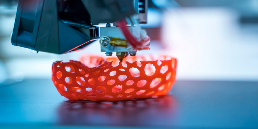
CNC machining can produce free-form surfaces. The key factors are tool access, tool diameter, collision clearance, and clamping. These are geometric limitations, not cost considerations. If the prototype design includes any of these characteristics, 3D printing is the practical choice—regardless of tolerance requirements.
CNC machining is well-suited for prismatic and rotational parts. It is also ideal for components with precise holes and threads. Thin walls with a defined thickness can also be machined effectively. This also applies to mating surfaces that connect to other components in an assembly.
These geometries account for the majority of functional prototypes in mechanical engineering, the automotive industry, medical technology, and aerospace.
Can the component be described by its outer shell? And by a set of machining operations? If so, CNC machining is the right process.
If it cannot be manufactured using subtractive methods without significant compromises in geometry, 3D printing is the right choice.
How do lead time and iteration speed differ between CNC machining and 3D printing?
CNC machining and 3D printing differ not only in terms of tolerances and materials. They also differ significantly in the time required. This applies to the entire process from order placement to prototype delivery, as it depends on how quickly design changes can be implemented.
CNC Machining: Turnaround Time and Number of Iterations
The lead time for CNC-machined prototypes is typically 3–5 business days for simple aluminum parts. Stainless steel, engineering plastics, and parts with more complex geometries or surface treatments generally require 5–10 business days. A change in geometry requires a revised drawing or 3D file, a new quote if necessary, and a completely new production run. For prototypes in early design iterations, this is a significant time factor per cycle.
3D Printing: Turnaround Time and Iteration Effort
3D printing often offers shorter turnaround times. Simple parts produced using FDM or SLA are often available within 1–2 business days. After changes are made, it may be necessary to recheck the data, reorient the part, reslice it, plan support structures, allocate build volume, and prepare a quote.
Setup work is usually less conventional, but it’s not „zero setup work.“ This makes 3D printing the faster choice for multiple consecutive iteration cycles.
Recommended Iteration Strategy
In practice, hybrid workflows have proven effective in many development projects. During the initial iteration phases, 3D printing is the faster and more cost-effective choice, as these phases are used to validate geometries, ergonomics, and component relationships.
Once the geometry has been finalized and functional tests, assembly fit, or initial prototype inspection are due, it makes sense to switch to CNC machining. This is because, from this point on, material properties and dimensional accuracy become critical. This transition is not an either/or decision, but rather a deliberate phase decision within the development process.
Quick Decision: Which Procedure for Which Case?
Situation |
Recommendation |
Typical delivery time |
| Geometric validation—appearance doesn't matter | FDM Printing | 1–2 days |
| Geometric validation, good surface finish | SLA printing | 1–2 days |
| Complex geometry, functional part made of plastic | SLS Printing | 2–4 days |
| Metal part with a tolerance of ±0.1 mm | CNC Aluminum | 3–5 days |
| Metal part with a tolerance of ±0.02 mm | CNC Steel / 5-Axis | 5–8 days |
| Material equivalent to production parts, functional tests | CNC-machined from original material | 3–7 days |
| Metal part with an internal channel | DMLS Printing | 5–10 days |
Estimated prices for individual prototypes. Costs depend on geometry, material, and quantity.
Manufacturing Products and Prototypes with FACTUREE
FACTUREE is a digital procurement platform for engineering drawings that offers a wide range of manufacturing solutions. Through our network of over 2,000 partners, we enable the efficient production of products based on your digital models.
By analyzing your CAD data, you can source individual prototypes, initial samples, and small-batch production runs in all common metals and engineering plastics directly through FACTUREE.
At FACTUREE, prototypes can be seamlessly combined with surface treatments such as anodizing, powder coating, and electroplating, as well as with a direct transition to series production—all from a single source.
The benefits of sourcing prototypes through FACTUREE: Network of qualified, certified prototype manufacturers (ISO 9001, AS9100, NADCAP) | Quotes for CNC, sheet metal, 3D-printed, and injection-molded prototypes available in as little as 24 hours | Direct DfM feedback on tolerances, wall thicknesses, material suitability, and thread characteristics before production begins | Delivery in as little as 3 business days for CNC prototypes made of aluminum | Complete documentation available upon request: Material certificates according to EN 10204, initial sample test report, dimensional inspection report | Seamless transition from prototype to small-batch and mass production—same point of contact, same quality processes.
Editorial Note: This guide was developed in collaboration with FACTUREE’s manufacturing technology experts, who draw on years of experience in coordinating certified coating processes. We review our content according to internal quality standards and regularly verify it against current DIN standards.